Efficient cooling of product is accomplished by particle
contact with the heat exchange surface, therefore, a relatively long total time of retention
of the particle in contact with the rotor surfaces is required. Contact must be continuous
and short duration, so that all particles may come in contact with the heat exchange surface
area. The ideal condition would be for the product to be in a fluidized state and highly
flowable.
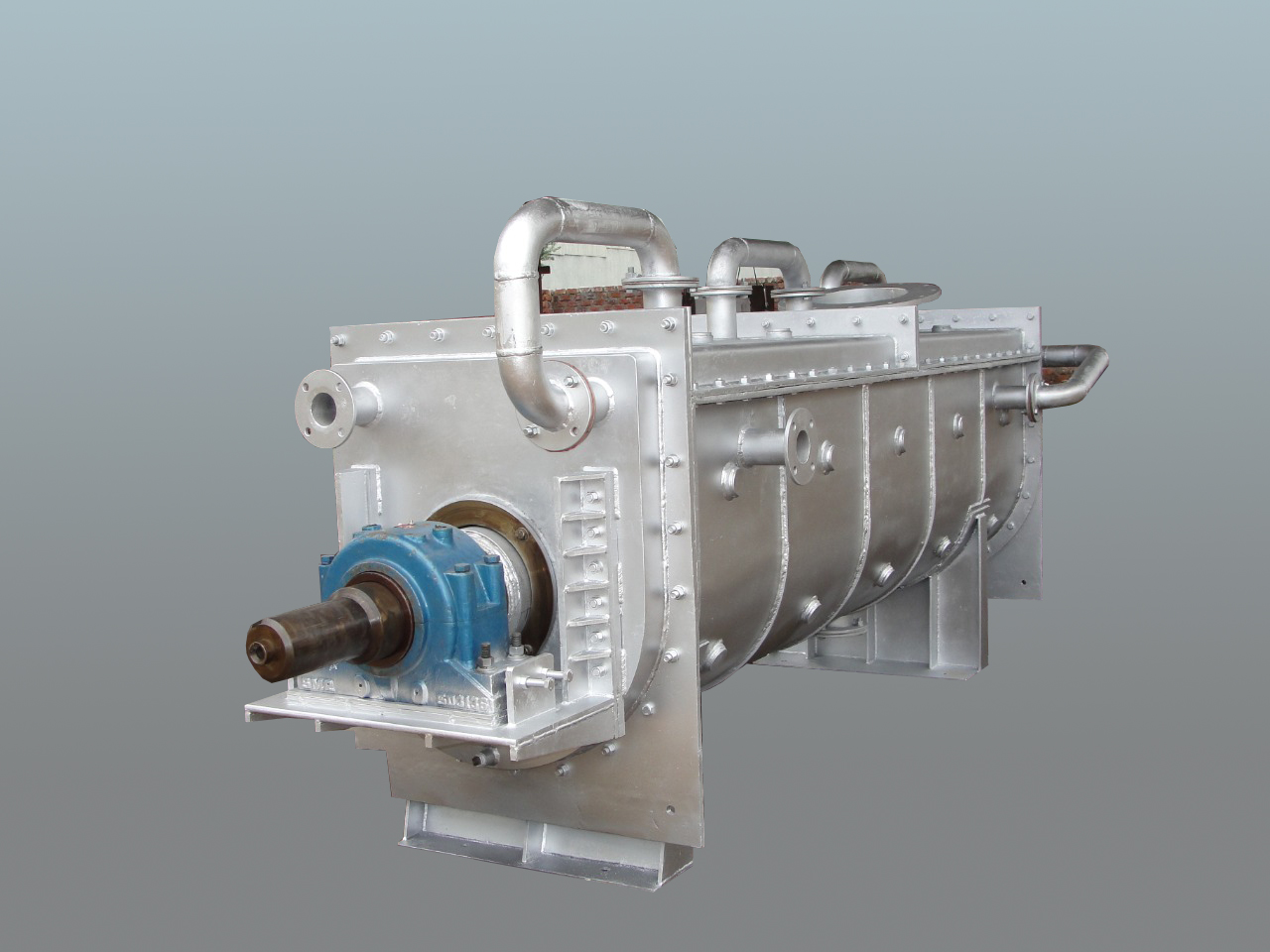
POWERCON provides a wide range of models and types of Holo-Screw Coolers custom designed
and built according to customer provided specifications.
Ash cooling screws are typically designed to handle boiler ash with a discharge temperature of up
to 950 Degree C and cooling it down to 150 Degree C or less so it can enter the ash handling
system.
Solid Stainless Steel Helicoid Flight construction at the inlet section of the screw rotor.
-
Stainless Steel can withstand the high temperatures in the inlet section of the cooler.
-
Reduces potential leaks in the inlet section of the screw rotor due to thermal stress
and deformation.
-
Increases the life of the screw rotor.
-
Decreases maintenance cost and weld repair.
-
Hard face overlay procedures are utilized to increase the wear resistance of the
flights.
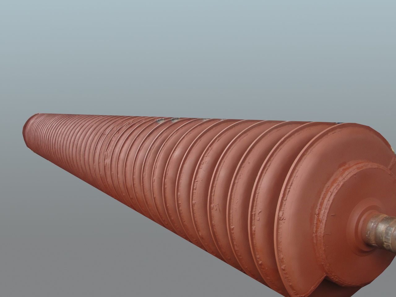
Hollow Flight construction is utilized on the remainder of the rotor.
- Hollow flights allow the cooling
medium to flow through the flights for increased heat transfer surface area.
- Single pad design allows expansion
and contraction while minimizing stress in the weld joints.
- hard face overlay procedures are
utilized to increase the wear resistance of the flights.
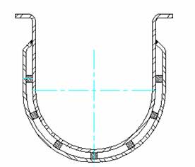
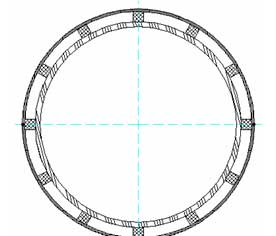
Jacketed Housings Cross-Sections.
Jacketed housing increases the cooling capability of the processor. Increases the life expectancy
of the housing by keeping the carbon steel in operational temperature limits.
The successful operation of a Hollow Screw Processor for cooling ash in Fluidized Bed Combustion
Technologies is dependent upon the ability to overcome the extreme environment at the inlet
section of the screw rotor.
Secondary in the design, you must consider the heat transfer capabilities of the processor as a
time dependant variable and all factors must be taken in consideration. These factors vary from
heat transfer surface area requirements, performance per square foot of area, fouling of the
rotor due to ash build up and fouling of internal heat transfer area due to scale and oxidation.
ADVANTAGES OF WATER-COOLED SCREW COOLERS -
1) System Space Requirement -1000 mm x 4500 mm ( Depends on Inlet C‐C ) x 1500 mm ( It varies with
System Layout -requirements)
2) Inlet & outlet Points - System / Single Water Cooled Bed Ash cooler can accommodate more than
1 inlet Point with flexibility to deliver point.( The delivery Point can be. extended on
requirement of site location
3) Recycling of cooling Media Possibility - Water cooled bed Ash cooler media water can be
recycled by Draining the same water in free Space tank and pumped once again .
4) Consumption of media used - Water cooled bed ash Cooler water can be consumed hardly by
evaporation and loss of volume is 1 to 5 %
5) Effects on Boiler system - Water cooled bed Ash cooler works- independently and it has no
connection with running of boiler , and drained water gets recycled independently , i.e. NO
Process involved of Boiler. Thus Boiler efficiency does not affect by any menace , The Boiler
can work independently even if The Bed Ash cooler under break Down and no need of stoppage of
Boiler.
6) Effects on Boiler structure & internal parts of boiler and its efficiency - Water Cooled Bed
ash cooler ,Water media is directly discharged to free space , does not affects any apart of
boiler. Thus boiler efficiency does not affects anyway.
7) Effects on Season Time - Normally the ambient temp Water is used , hence there is no effects
in operation of the system in any season.
8) System Operation ‐Programme - Water cooled System requires , few controls like ,Pressure of
water , detection of water flow and rotation of Screw
9) Maintenance Cost - Mainly Damages take place to internal Screw after Long running Time ,
Approx. 10 years span , in such case Complete shaft may require to replace . In Normal course ,
greasing , bearing . Chain sprocket over all maintenance is required.
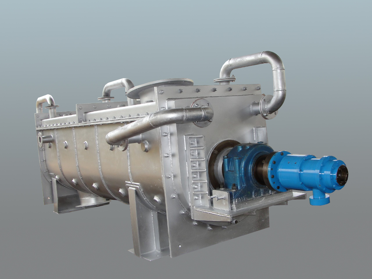
10) Material of construction - Normally The Water cooled systems are made through SS material ,
which anti corrosive and heat resistance , Gives better life span , about 10 years.
11) Method of construction - Water cooled Cooler can be constructed through Stationary casing and
rotating Screw or Vic versa is Rotating casing with stationary in built screw with housing
12) Heat transfer Area / contacts - Due to circular / U trough Casing and rotating Screw hollow
water filled Screw flights , the each and every particle has chance to come in contact with
Surface for heat Extraction , thus the % of particles getting cooled is High and heat transfer
is High. Finally about all ash gets cooled and does not left Hot / unearthed portions
13) Pollution Concerns - Water cooled cooler are Dust tight , totally enclosed and very rear
chances to come the dust form any other areas excluding Inlet Section and outlet Sections. Thus
environmentally very useful .The Noise level is very Low , noise level Operation is possible.
14) Power Consumption - Power consumption is almost same in average with Single Electrical Motor.
EQUIPMENTS INCLUSION DETAILS-
Powercon Equipments – Bed Ash Cooling System Comprises following Equipment’s-
- Suitable temperature - Slide gate
cum Isolation gates immediate after – Bed Ash drain Outlets .
- Surge Hopper of Desired Capacity
immediate after – Suitable Slide Gate -Operator for High Temperature.
- Slide Gate / Rotary Feeder to get
discharge hot material further in BAC ( Bed Ash Coolers)
- BAC- Bed – Ash-Coolers of desired
Capacity with desired inlet to outlet centre to centre.
- Isolation / Slide gate at Discharge
of BAC
- Intermediate Chutes / Y Chutes
- Cross Collecting Drag Chain feeders
with water cooling Jackets.
- Elevated Drag Chain feeder with
water cooling Jackets ,to lift the cooled ASH -towards Storage Silo.
- Suitable Storage Capacity SILO for
storage of one Shift Bed Ash.
- Suitable Dust extraction System .
- Suitable Isolation cum bed ash
discharge Control – Live Bottom Screw / Slide gate / Rotary Feeders.
- Suitable Discharging capacity – Dust
conditioner , to discharge the material towards discharging Transport Vehicle / trucks
- Suitable Instruments like , Flow
Control , Flow Detectors , temperature Detectors , Level sensors , Air Pulsing system
etc
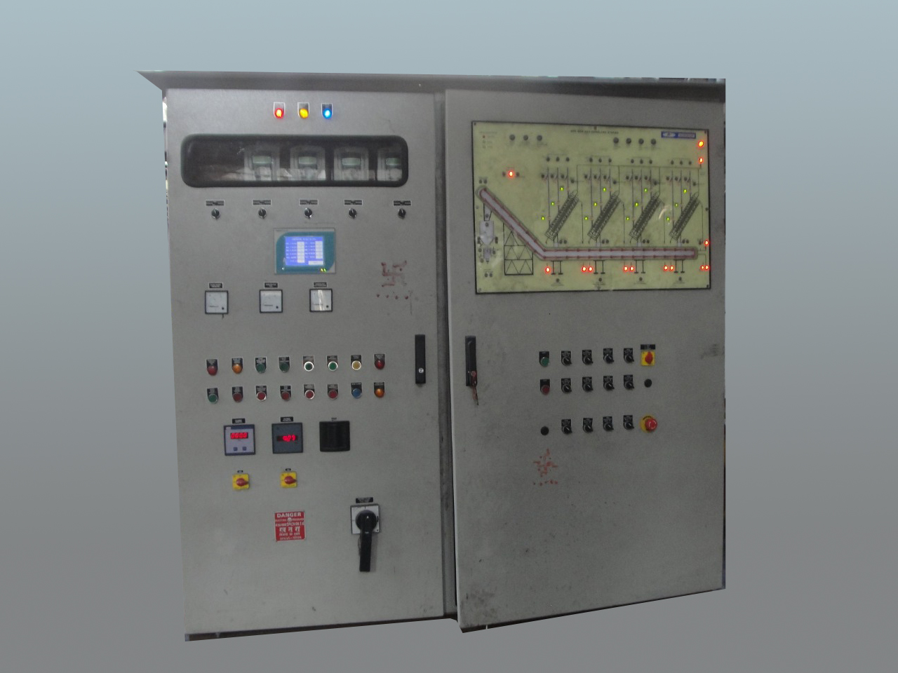
- Suitable Integrated PLC base Control
Panel.

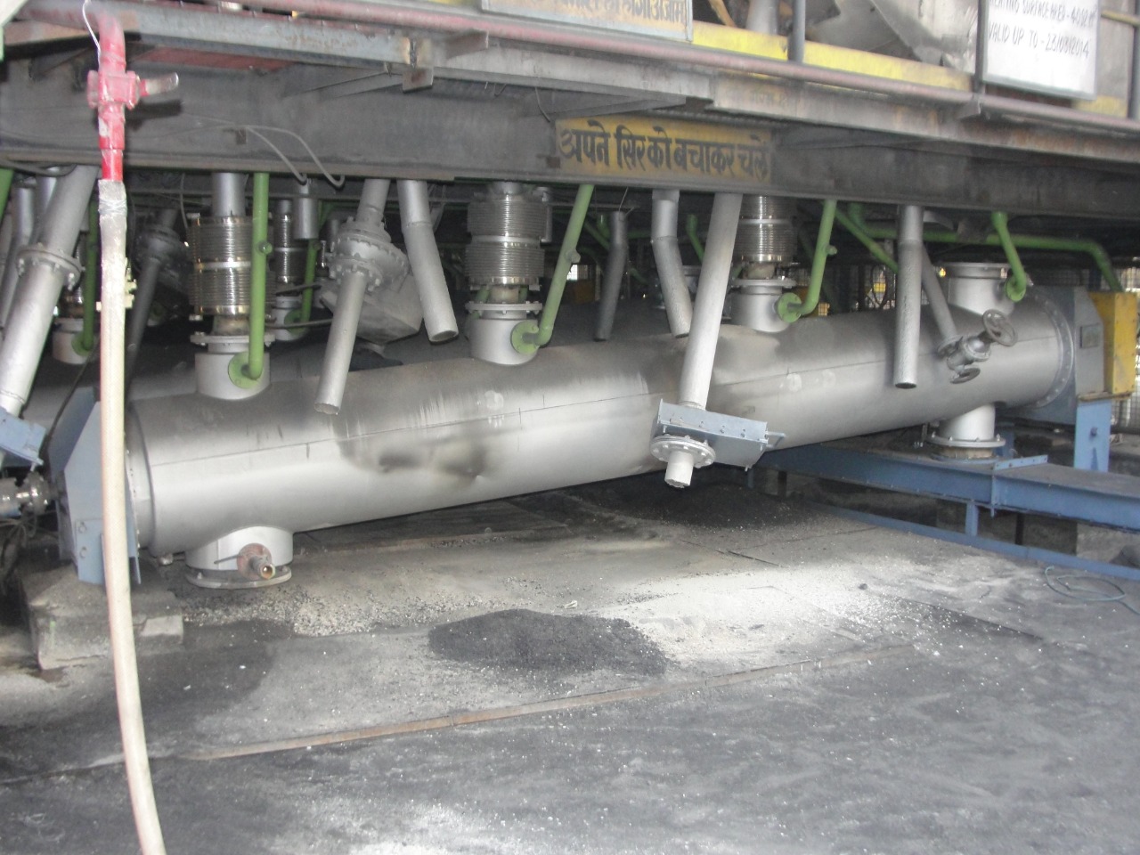
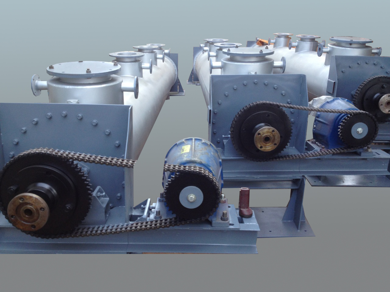
ACTAUL SITE INSTALLATION PHOTO
WORKING STAGES –
1) The RED HOT about. 950 Deg. C material is being allowed to flow towards discharge
through suitable slide gate opening towards the SURGE hopper Assembly. Approximate
capacity of SURGE hooper is about 1or 2 minutes storage with respective to desired
Capacity.
2) The stored material in Surge Hopper is being getting discharge by Slide gate / Rotary
feeder with controlled cycles opening towards BED ASH COOLER inlet .
3) Suitable Metallic Rubber bound Expansion Joints are provided in between the BAC and
Boiler outlets to accommodate vertical expansion effect in the assemblies .
4) The material get entered in BAC and due to continuous new surface in contact with HOT
Bed Ash , Heat get extracted through out Bed material , resulting in cooling down the
temperature of. The BED ASH.
5) The time required in cooling the BED ASH up to desired temperature at outlet of BAC is
being calculated and BAC Speed is designed accordingly .
6) In case of BAC assembly having short length due to site constraint in inlet to outlet , the
bed Ash is being get forward and reverse by rotating the screw in reverse and forward motion ,
This motion is designed with minutes detail and make sure of new fresh LOT of bed ash comes in
BAC while OLD LOT of Bed Ash getting. Discharged. , Specifically care has been taken to maintain
the desired capacity discharged throughout cycles .
7) Thus we get RED hot Bed Ash Temperature form 950 Degree C to. About. 150 Degree C at outlet of
BAC , The further BAC discharge is being get discharge in common Cross Collecting DCF to take
the material towards ELEVTED DCF and further to Storage SILO.
8) The inlet temperature of Bed Ash at inlet of cross collecting DCF is about 150 Degree C and
same is being. Reduced up to about 75 Degree C . The Cross colleting DCF is. Also having water
Jacket Assemblies throughout travel. I.e. Inlet to outlet areas .
9) The 75 Degrees C Bed Ash material further enters in Elevated DCF , to take towards Storage
Silo ,The 75Degree C temperature is further get down up to ambient / below ambient while. It
enters in Storage SILO. The Elevated DCF is also being constructed with water Jacket Assemblies.
10) The Storage SILO is so designed to accommodate about one Shift Bed ash material ,
11) The Storage Silo is being designed with auto infra-red sensors to control the LOW/ MEDUIM and
HIGH levels of bed Ash in SILO.
12) Thus depend upon the level sensors indication the draining cycles of Bed Ash is controlled.
Through PLC logic , That allows system to RUN /STOP up tp safer level indication of Bed Ash in
Storage SILO.
13) The Storage SILO is being also taken care by introducing the DES ( Dust Extraction System) to
avoid Dusty atmosphere inside the SILO or outside while Discharging the Bed Ash. The DES
recycles the collected powder form bed ash again in main stream i.e. Storage SILO.
14) The Storage SILO is. Also being designed and manufactured by providing Vibration Pads /
Pneumatic air pulsing System to get the free discharge of bed Ash towards disposal vehicles ,
The Vibration System does not allow to stagnate the bed Ash in Storage SILO.
15) The Stored bed Ash is being gradually discharged in Dust Conditioner assembly to get
discharged in disposal vehicles . The Dust Conditioner assembly is water sprinkling mechanism to
add the moisture id. Dry – Powder from Bed Ash. Thus adding moisture / Water inndrg bed Ash ,
the bed Ash does not get spillages in atmospheres and thus we reduce the pollution .
16) The isolation get / Live bottom Scree / Rotary feeder is. Being provided in between SILO
Discharge Outlet and Dust Conditioner Inlet Section.
Thus the 950 Degree C Bed Ash material gets cooled up to or below ambient and safe disposal to
RED HOT Bed Ash is. Being complete.
There are many instruments are being installed in System , like water flow detector , Water
temperature detector , Bed Ash Inlet temperature and. Discharge out let temperature , level
sensors ,motion detectors etc , This all system is. Being controlled through PLC base LOGIC and
mimicry panel.